Archived: Loading the code onto APM2.x
What you’ll need:
Setting up the software drivers
First, download and install Arduino (see links above). If you’ve never used Arduino before, please use these setup instructions to become familiar with Arduino basics.
Next, set up the drivers for the USB interface to APM. Most people will use a regular USB-A to miniB cable (regular USB on one side, mini USB on the other) to connect to APM via the IMU shield, but if you’re not using that shield you can use a FTDI cable. Pictures showing how to plug in these cables are below.
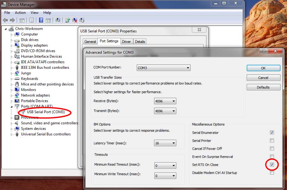
When you plug APM or the FTDI cable the first time to your PC, Windows 7 should recognize the FTDI USB-to-serial chip and install the right drivers, but if it doesn’t or if you’re using an earlier version of Windows, you should download and install the appropriate driver for your Operating System from here. Once you’ve done so, reboot your PC and plug in the cable again. It should be recognized and show up in your Windows Device Manger (which you can find in the Windows Control Panel) as shown below (your COM port will probably be a different number; it’s assigned by Windows based on how many other devices you’ve connected). That’s the COM port you’ll use in Arduino and all other USB interactions with APM.
Note: if you’re using the FTDI cable, you must go to the Control Panel/Device Manager and make a change to the COM port assigned to the FTDI/USB cable. Find the USB Serial Port entry as shown here (your FTDI may have been assigned to a different port than the 3 shown below; it doesn’t matter what number it’s given) and under Properties/Port Settings/Advanced, ensure that the “Set RTS On Close” box is checked, as shown below. Once you’ve made this change once, you won’t have to do it again.
Connecting the cable
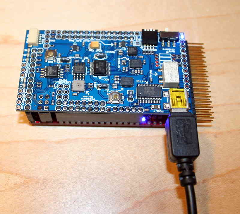
The FTDI or USB cable will provide sufficient power for desktop use, but will probably not drive more than two regular servos. If you want to drive more servos than that or if you’re using digital servos, you’ll need to have an additional power supply (usually an ESC connected to one of the APM servo outputs).
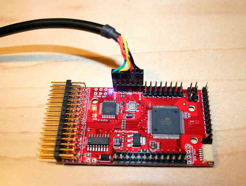
If you’re using a USB cable, connect it here:
If you’re using an FTDI cable, connect it here, noting the marking for the black and green sides of the cable:
Setting the Sketchbook folder
Next you must define the folder Arduino will use for its “sketches” (Arduino-talk for the set of files that compose a program) and libraries
Create a folder someplace where you can find it, perhaps in your
Documents folder or even on your desktop. (If you’ve been using Arduino,
you probably have this set up somewhere already). Launch the Arduino IDE
and open the Preferences dialog. Set the sketchbook location to
theSketchbook folder you created or are using. Here’s where I have
mine:
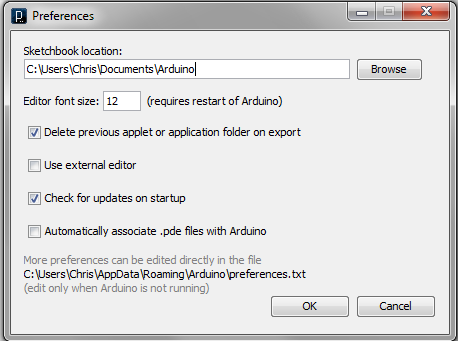
Once you’ve changed that directory, you must close Arduino and restart it for it to be recognized.
Setting the board type
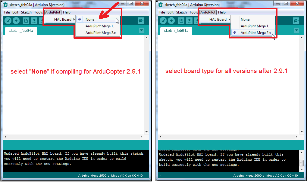
In our modified version of the Arduino IDE there is a new “ArduPilot” menu which allows you to select the board type.
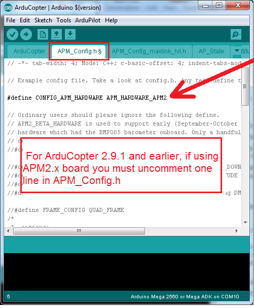
For Copter version 2.9.1 and earlier you should select the “None” from this menu and then ensure that under Tools, Board is “ArduinoMega 2560 or Mega ADK”. If you are using an APM2 you will also need to uncomment line 5 from APM_Config.h (see bottom screenshot)
For versions later than 2.9.1 you should set the “ArduPilot”, “HAL Board” to either “ArduPilot Mega 1” or “ArduPilot Mega 2.x” depending on which board you are programming.
Note
You will need to restart your Arduino IDE after changing the above.
