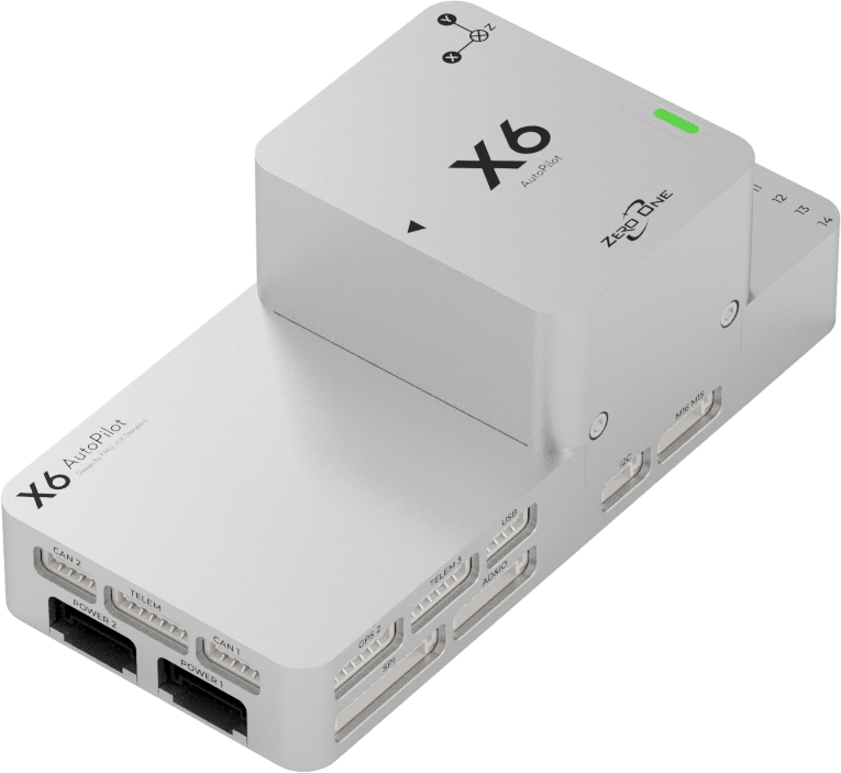
ZeroOneX6
The ZeroOne X6 is a flight controller manufactured by ZeroOne, which is based on the open-source FMU v6X architecture and Pixhawk Autopilot Bus open source specifications.
Features:
- MCU
STM32H753IIK6 32-bit processor running at 480MHz
STM32F103 IOMCU
2MB Flash
1MB RAM
- Sensors
- IMUs:
Internal Vibration Isolation for IMUs
IMU constant temperature heating(1 W heating power).
Triple Synced IMUs, BalancedGyro technology, low noise and more shock-resistant:
IMU1-ICM45686(With vibration isolation)
IMU2-BMI088(With vibration isolation)
IMU3-ICM45686(No vibration isolation)
- Baros:
Two barometers:2 x ICP20100
Magnetometer: Built-in RM3100 magnetometer
- Interfaces
Ethernet
Micro-C USB
7 UARTs, 3 with hardware flow contrrol
Safety Switch
2 CAN Power Monitor inputs
2 CAN ports
SPI and I2C ports
16 motor/servo outputs, 8 supporting BiDirDShot, 14 suporting DShot
Pinout
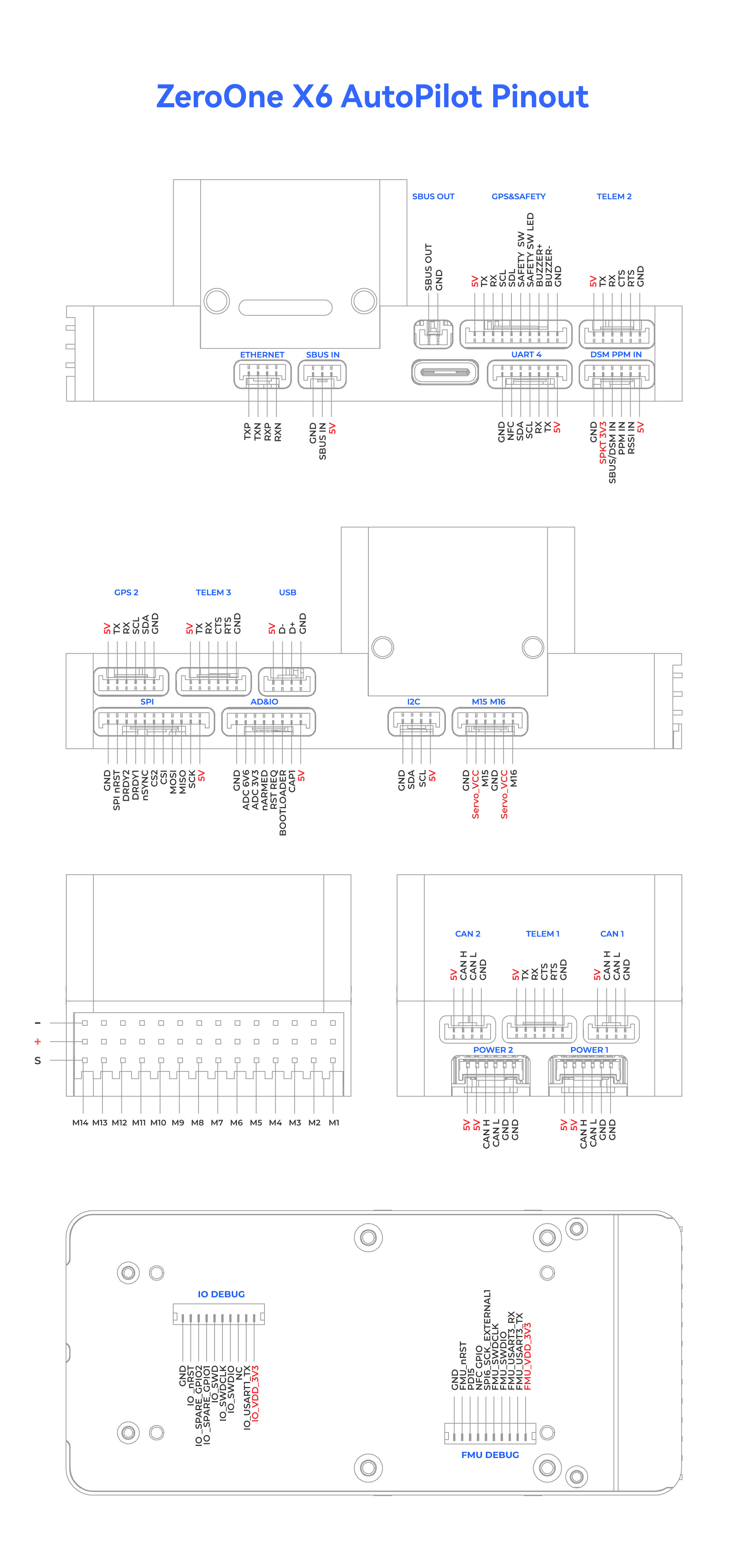
UART Mapping
The UARTs are marked Rn and Tn in the above pinouts. The Rn pin is the receive pin for UARTn. The Tn pin is the transmit pin for UARTn. All are DMA enabled.
SERIAL0 :USB OTG1
SERIAL1 :UART7 Telem1
SERIAL2 :UART5 Telem2
SERIAL3 :USART1 GPS1
SERIAL4 :UART8 GPS2
SERIAL5 :USART2 Telem3
SERIAL6 :UART4 USER
SERIAL7 :USART3 FMU DEBUG
SERIAL8 :USB OTG-SLCAN |
RC Input
The remote control signal should be connected to the SBUS RC IN port or DSM/PPM RC Port.It will support ALL unidirectional RC protocols. For FPort, CRSF/ELRS, SRXL, etc. any UART can be used, see Radio Control Systems for more information.
PWM Output
The X6 flight controller supports up to 16 PWM outputs. First 8 outputs (labeled 1 to 8) are controlled by a dedicated STM32F103 IO controller. The remaining 8 outputs (labeled 9 to 16) are the “auxiliary” outputs. These are directly attached to the STM32H753 FMU controller.
All 16 outputs support normal PWM output formats. All 16 outputs support DShot, except 15 and 16. Outputs 1-8 supoort BiDirectional DShot.
The 8 IO PWM outputs are in 4 groups:
Outputs 1 and 2 in group1
Outputs 3 and 4 in group2
Outputs 5, 6, 7 and 8 in group3
The 8 FMU PWM outputs are in 4 groups:
Outputs 9-12 in group1
Outputs 13 and 14 in group2
Outputs 15 and 16 in group3 (PWM only)
Channels within the same group need to use the same output rate. If any channel in a group uses DShot then all channels in the group need to use DShot.
GPIO
All PWM outputs can be used as GPIOs (relays, camera, RPM etc). To use them you need to set the output’s SERVOx_FUNCTION to -1. The numbering of the GPIOs for PIN variables in ArduPilot is:
| IO Pins | FMU Pins | |||||
|---|---|---|---|---|---|---|
| Name | Value | Option | Name | Value | Option | |
| M1 | 101 | MainOut1 | M9 | 50 | AuxOut1 | |
| M2 | 102 | MainOut2 | M10 | 51 | AuxOut2 | |
| M3 | 103 | MainOut3 | M11 | 52 | AuxOut3 | |
| M4 | 104 | MainOut4 | M12 | 53 | AuxOut4 | |
| M5 | 105 | MainOut5 | M13 | 54 | AuxOut5 | |
| M6 | 106 | MainOut6 | M14 | 55 | AuxOut6 | |
| M7 | 107 | MainOut7 | M15 | 56 | ||
| M8 | 108 | MainOut8 | M16 | 57 | BB Blue GPo pin 3 | |
| FCU CAP | 58 | |||||
Battery Monitoring
The X6 flight controller has two six-pin power connectors, supporting CAN power modules. These are set by default in the firmware and shouldn’t need to be adjusted.
Compass
The X6 flight controller built-in industrial-grade electronic compass chip RM3100. Users may want to disable this and use an external compass in case of motor noise interference.
Analog inputs
The X6 flight controller has 3 analog inputs.
ADC Pin12 -> ADC 6.6V Sense
ADC Pin13 -> ADC 3.3V Sense
RSSI input pin = 103
5V PWM Voltage
The X6 flight controller supports switching between 5V and 3.3V motro/servo output levels. Switch the output pulse level by configuring parameter BRD_PWM_VOLT_SEL. Set 0 for 3.3V and 1 for 5V output.