LTM Telemetry
Protocol overview
Lightweight TeleMetry protocol (LTM) is one-way communication protocol - data downlink from vehicle - that allows you to send most important vehicle data at low band-width / low baud rate, usually at 2400 bauds.
Protocol was introduced by KipK and is used in his Ghetto Station.
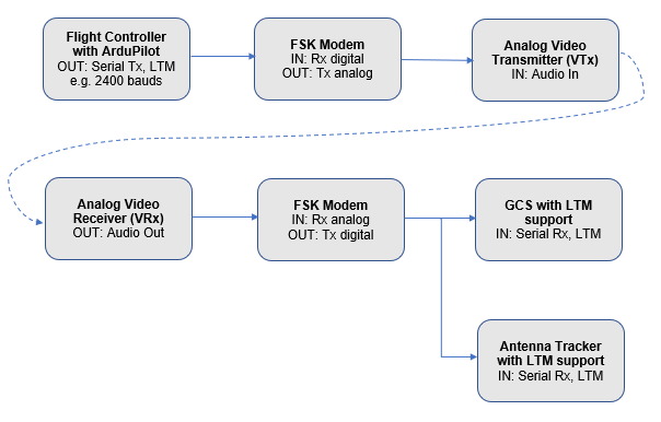
Typical use-case is antenna tracking when serial telemetry data from Flight Controller (FC) are transformed by Frequency Shift Keying modulation (FSK) modem to sort of audio signal, that is transferred by audio channel of video transmitter to video receiver on ground side. Consequently it’s converted back to digital signal by other FSK modem and processed in antenna tracker (AT) and possibly in Ground Control Station (GCS).

Block diagram of common LTM telemetry setup
- Implemented protocol frame types at ardupilot side
- G-Frame (GPS)
contains latitude, longitude, GPS ground speed, no. of visible sats, GPS fix type
size 18 Bytes, sent at 2 Hz
- A-Frame (Attitude)
contains vehicle attitude, heading
10B / 5 Hz
- S-Frame (Status)
contains battery voltage, current, receiver RSSI, airspeed from AHRS
11B / 2 Hz
- Protocol limitations
GPS fix data type uses only 2 bits - list of possible values is 0 (No GPS fix), 1 (2D fix), 2 (3D fix). GPS fix values above 2 are mapped to value 2.
- Links related to LTM telemetry
GhettoStation antenna tracker: https://github.com/KipK/Ghettostation
iNAV documentation for LTM protocol: https://github.com/iNavFlight/inav/wiki/Lightweight-Telemetry-(LTM)
Protocol overview at quadmeup.com: https://quadmeup.com/ltm-light-telemetry-protocol/
LTM-to-MAVLink converter for Arduino ProMini or ESP8266: https://github.com/vierfuffzig/LTM2MAVLink
Configuration
Parameter SERIALX_PROTOCOL has to be set to value 25 to enable LTM output from FC on given serial port. Note that only one LTM output port is supported. If you set multiple serial ports to output LTM, only the first one found during serial driver initialisation will actually be assigned to output LTM telemetry.

LTM configuration screenshot from Mission Planner
Note
Don’t forget to set your LTM telemetry port’s baud rate to an appropriate value. If you are using FSK modems, baud rate value depends on capability of modems.
Additionally, not all of your autopilot’s serial ports support the lowest possible baud rate setting of 1 ( = 1200 baud). On STM32F4xx and F7xx based autopilots, these typically are USARTs 1 and 6 that run on the full system clock. If set to 1200 baud, these ports will default to 19200 baud instead. If you have issues getting correct LTM telemetry output at 1200 baud, try using a serial port other that USART 1 or 6 or opt for 2400 baud instead. On STM32H7-based boards, 2400 baud is lowest supported UART baudrate. Check your flightcontroller’s hardware page for further reference on UART to SERIALn mapping.
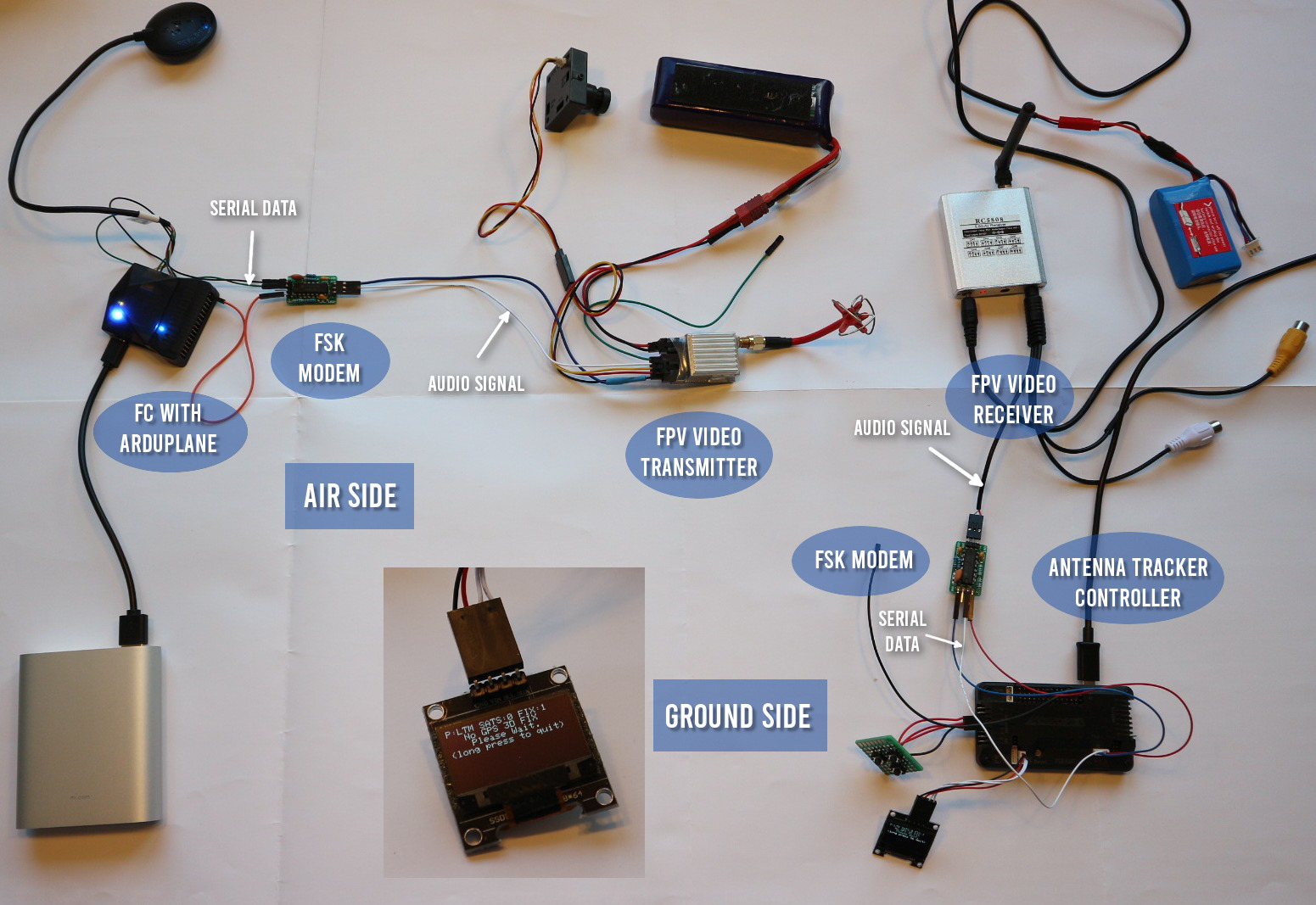
Usage example with FPV video transmitter

LTM telemetry wiring example for Plane
FSK modem example with TCM3105
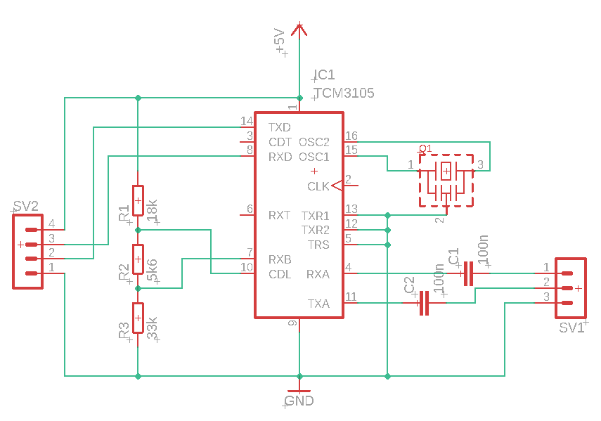
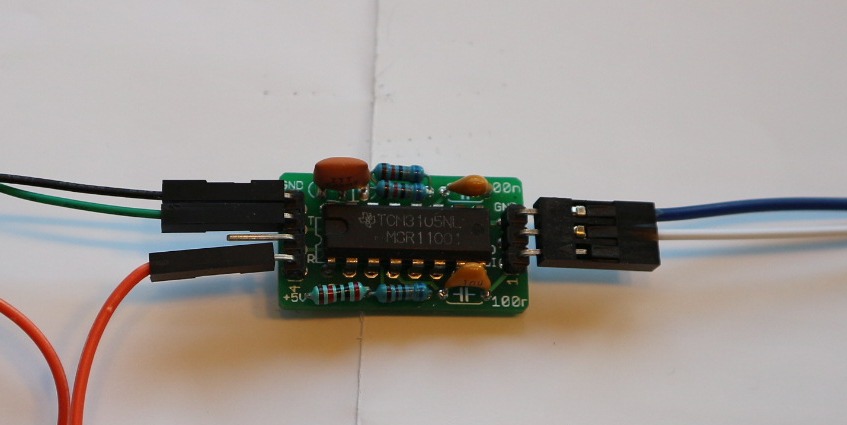
One of the possibilities for FSK modem is to use chip TCM3105. Eagle files for modem schematics and board can be found at https://github.com/kh4/FSK_modem
This modem can work at 1200 or 2400 bauds, baud rate depends on used oscillator.

FSK modem with TCM3105 schematics example

FSK modem with TCM3105 photo
Tip
Use 8 MHz oscillator to make modem work at 2400 bauds.