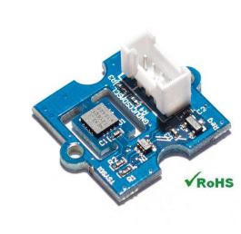
Temperature Sensors
ArduPilot supports up to nine individual temperature sensors:

In addition, analog temperature monitors and DroneCAN based sensors can be used.
ArduPilot already has numerous possible sources for temperature reports: ESCs, Smart Batteries, Motor EFI and these independent sensors can be used to replace those devices temperature reports which already exist in ArduPilot. They can also just be logged.
I2C Sensor Setup
Attach the sensor to one of the autopilot’s I2C ports using SDA and SCL pins. Then set (examples shown for the first sensor):
TEMP1_TYPE = 0:Disabled, 1:TSYS01, 2:MCP9600, 3:MAX31865, 4: TSYS03, 7: MLX90614
TEMP1_BUS = the I2C port on which the sensor is attached (0-3).
TEMP1_ADDR = the sensor’s I2C address (0-127).
TEMP1_SRC = the temperature reporting device type that should have its temperature report replaced with this sensor’s.
TEMP1_SRC_ID = identifies the individual device, of the above type, that should have its report replaced.
Note
Each I2C device on any single bus must have a unique address. If more than one of the same type of I2C temperature sensor is used, ensure each is configured with a unique address. Some breakout boards include jumpers for this purpose. Refer to the product datasheet for specific instructions regarding I2C address configuration.
Note
The MAX31865 is an SPI device, which uses the same parameters and basic configuration procedure as I2C sensors but must be connected to an SPI port rather than an I2C port. Some autopilots do not expose an external SPI port, in which case the MAX31865 cannot be easily used.
Note
The MLX90614 sensor is an infrared thermometer for non-contact temperature measurements. Its I2C address is 90 so TEMP1_ADDR = 90 for this type of sensor.
Analog Sensor Setup
Attach the sensor to an analog input pin (an unused rssi input, analog airspeed input, battery voltage input, or current monitor input pin, for example). The pin number can be determined from the autopilot’s wiki page. Use care not to exceed the pin’s rated voltage (typically 3.3 volts) with the sensor output. Then set (examples shown for the first sensor):
TEMP1_TYPE = 5 : Analog
TEMP1_PIN = the analog pin number (for example: 2:Pixhawk/Pixracer/Navio2/Pixhawk2_PM1, 5:Navigator, 13:Pixhawk2_PM2/CubeOrange_PM2, 14:CubeOrange, 16:Durandal, 100:PX4-v1, etc.)
The output voltage vs temperature curve of the sensor can be adjusted to match its characteristic via a polynomial (up to 4th order). Fit the curve via the product datasheet, a spreadsheet application, MATLAB, Python/numpy, etc:
deg = a0 + a1*voltage + a2*voltage^2 + a3*voltage^3 + a4*voltage^4
DroneCAN Setup
Make sure the CAN port is setup. (example below for first CAN port using first driver):
CAN_P1_DRIVER = 1 (First driver)
CAN_D1_PROTOCOL = 1 (DroneCAN)
Then set (examples shown for first sensor):
TEMP1_TYPE = 6 (DroneCAN)
Logging
Several peripherals have the possibility of reporting temperature if their hardware permits: ESCs, EFIs, Smart Batteries, etc. However, if their hardware does not include a temperature sensor, it’s possible to redirect a discrete temperature sensor’s report to be included with another device’s report. We will use the first temperature sensor below as an example.
TEMP1_SRC will designate which device’s temperature report will be replaced by this temperature sensor’s data. ie: if set to 1, then an ESC’s report of temperature(usually null due to lack of hardware capability).
TEMP1_SRC_ID replaces a specific instance of a system component’s temperature report with this temp sensor’s. ie: if set to 4, with the above param set to 1, the fourth instance of an ESC (ie 4th motor/servo output with a motor/throttle function) will have its temperature report replaced.
TEMP_LOG = 0: No logging, 1: Log temperature reports from all temperature sensors, including those also being reported in other device reports, 2: Only those with
TEMPx_SRCset to NONE, eg. not being logged elsewhere.