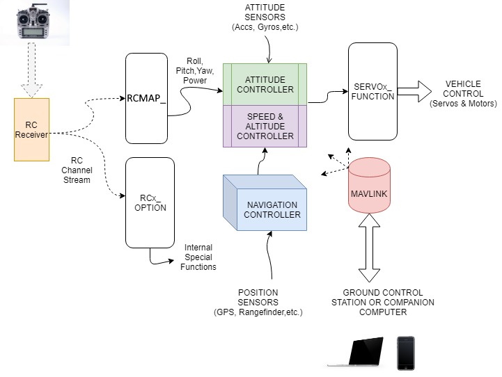
Simple Overview of ArduPilot Operation
This is a very basic overview of the functions of ArduPilot firmware running on an autopilot. Shown below is a simple block diagram of the basic functional operation. This will give you a better understanding of ArduPilot basic functions as you configure your system.

Basic Goal
The basic goal of the software is to provide control of the vehicle, either autonomously, or via pilot input through radio control transmitter or ground control station, or via companion computer on board the vehicle, any of which are optional, including only loading a fully autonomous mission on the vehicle for execution.
Inputs
Control inputs are input either by radio control receiver, or via MAVLink communication from telemetry or companion computers. The radio control receiver provides Roll/Pitch/Yaw inputs for desired attitude control, vehicle power (throttle), as well as control of operational modes and auxiliary functions. The radio control inputs for Roll/Pitch/Yaw/Throttle can be assigned to any radio control channel via the RCMAP_x functions. Auxiliary functions are assigned using the RCx_FUNCTION parameters.
Outputs
Outputs are provided to activate servos, motors, relays, etc. to control the vehicle. Any autopilot output can be assigned the desired vehicle control output function via the SERVOx_FUNCTION parameters. Note that outputs do NOT necessarily correspond to any RC input, unless their function is set to RCPassThru.
Sensors
Attitude, position, power system monitoring, and vehicle speed are provided by sensor inputs to the autopilot. All ArduPilot compatible autopilots have at least one or more accelerometers, baros, and gyros integrated onboard. Typically a GPS, and often, a Compass sensor is required. Usually these are provided externally. Some controllers have multiple instances of sensors for redundancy, a key feature of the ArduPilot software. Many sensors require a one-time calibration during the Mandatory Hardware setup step.